« June 2007 | Main | August 2007 »

July 2007 Archives

July 6, 2007

Interlude: Physical Wiring (Who Will Drive VCCOUT_D?)

Dear Reader: I have more grunt work to do before I've got my testbench in perfect order. This interlude describes a change I have to make in order to power the microcontroller on the f2013 board from the testbench, and eventually a power supply in the final application, rather than from a USB-derived power supply. Nothing very interesting here, but out of these nuts and bolts are built something interesting, eventually, I hope.

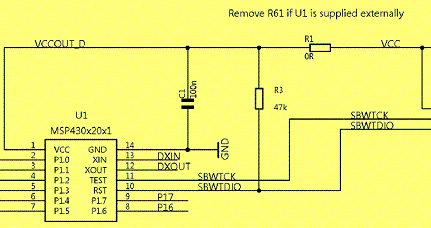
As shipped, the microcontroller on the f2013 board takes its power from the USB cable, which is very nice because it avoids the need for any sort of external power supply. But in the application I'm thinking of, there won't be a handy USB port; power will have to come from somewhere else. Fortunately, someone at Texas Instruments thought about this. In between the USB-derived +3.6V power supply ("VCC") and the microcontroller's pin 1 ("VCCOUT_D"), there's a 0-ohm resistor, R1. Check it out in this snippet of the f2013 schematic (they meant "R1", not "R61", in the note):

remove_r1_yellow.gif

(The full schematic is on page 8, over here.)

Here's another snippet of the schematic, showing how P1-P14 connect to the f2013 signals. P1, P2, ..., P14 connect to the micro's pin 1, pin 2, ..., pin14, and also to the handy 2x7 array of througholes on the f2013 board. Notice especially that P1 connects directly to VCCOUT_D.

legend.gif

In a previous episode, I removed one pin of the santa cruz board's connector, so that the 1c20's +5V would not connect to P1 - otherwise, I would have had a connection from the 1c20's +5V, through VCCOUT_D, to VCC (+3.6V) - that would have been bad.

In the testbench I'm constructing, the santa cruz board stands in for the universe, from the P.O.V. of the f2013 board. So, it would be a step in the right direction if VCCOUT_D came from the santa cruz board, rather than from VCC.

I have to make two hardware changes to drop my dependence on the USB-derived VCC:

  1. Remove R1, so VCC is disconnected from VCCOUT_D. This is a simple matter of breaking out the soldering iron and heating up R1 until it breaks loose.
  2. Connect a +3.3V power supply to santa cruz board J1 pin 2 (which, confusingly, connects to P1). Fortunately, the santa cruz board has a clearly labeled +3.3V supply rail, with handy through-holes. I ran a wire from that supply to J1 pin 2, and for all practical purposes, Bob was my uncle.

After making those two changes, I verified that the f2013 board does get power from the 1c20 board, that the f2013 can still be programmed via the IAR IDE over the USB cable, and that the f2013 can still drive the 1c20's LEDs. Success!

July 7, 2007

My Little GP1UE267XK

So, back to the concept. I'm adding remote on/off capability to my XBox, similar to what's described here. That site informs me that a 56KHz, 3.3V IR Detecting Unit is the one I want, and Sharp's GP1UE267XK looks ok. But, why not just use an IR phototransistor for the task? Here's a hint from the data sheet: the block diagram of the GP1UE267XK looks like this:

ir_detector.GIF

There's a lot going on here beyond simple transduction of infrared light into a flow of electrons. The end result of all that circuitry should be better noise resistance (fewer false triggers) and better detection of weak signals. Digikey sells the device for $1.08, and that seems like a pretty good deal to me.

Here's a good discussion of how IR remote controls work.

It's worth noting here that in choosing the GP1UE267XK, I'm already moving away from a general-purpose IR receiver design, because of the device's 56.8kHz center frequency. To get back to generality, I'd have to consider using pluggable IR receiver modules, specific to each application frequency, or the use of a more general-purpose receiver circuit.

Here's how the data sheet suggests hooking up the GP1UE267XK:

ir_electrical_hookup.GIF

The data sheet also has this advice, which I will surely follow to the letter:

ir_warning.gif

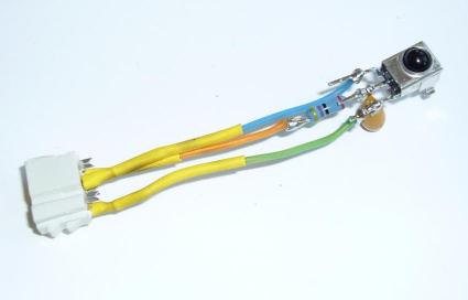
Now. The GP1UE267XK and its associated resistor and capacitor form a 3-pin module, which I've soldered to a connector:

ir_module.jpg

The IR module will plug into the santa cruz connector board, but where?

  • pin 3, GND (green wire): Easy, connect this to any handy ground point on the santa cruz board.
  • pin 2, Ve (orange wire): Also easy, connect to any +3.3V point on the santa cruz board.
  • pin 1, Vo (blue wire): Hm. This requires some thought. Connect it to one of the pins on the header that the f2013 plugs into?

I've decided. Vo will connect to a currently-unused santa cruz connector signal which drives the 1c20. Then I can route Vo through the 1c20 to any f2013 microcontroller pin. I can also use the 1c20 testbench circuitry to analyze the IR signal, or even create 1c20 testbench circuits to simulate known IR signals, for regression testing.

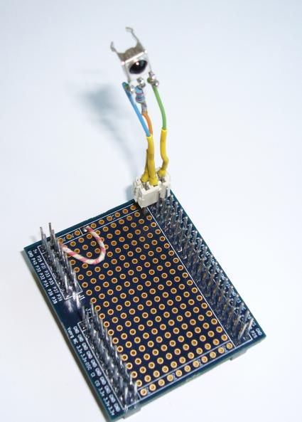
Here's the IR module, plugged into the santa cruz connector board:

ir_module_on_sc.jpg

Vo (blue wire) connects to the signal labeled "P0" on the santa cruz connector board silkscreen, which in turn connects to 1c20 pin T15.

New testbench time! This one will be revision "03", and it'll simply connect the signal from the IR module, through the 1c20, to the 8 LEDs. The goal here is just to demonstrate that the IR module is alive and can receive a signal from the remote. Here's the system in action:

Success! The LEDs blink in response to a signal from the remote. But what's the encoding protocol? What codes are sent for each key? Is there parity or some other error detection scheme embedded in the data? To find out all this and more, I'll need the assistance of a mighty tool, SignalTapII(tm). Next time!

Edit: forgot the testbench files.

July 15, 2007

This is Signal Tap

Here's what the Mighty Altera Corporation has to say about signaltap:

The SignalTap® II logic analyzer is a second-generation system-level debugging tool that captures and displays real-time signal behavior in a system-on-a-programmable-chip (SOPC), giving you the ability to observe interactions between hardware and software in system designs.

Right right right. For my purpose, signaltap is just an on-FPGA digital sampling scope, whose UI happens to live in Quartus. I'll use it to study the data stream from the Xbox remote control.

So, how do I use this thing? Three steps:

  1. Define the probe
  2. Connect the probe to my signals
  3. Capture and view trace data

1. Define the probe:

Quartus provides a GUI for step-by-step definition of signaltap probe parameters, in the menu:

Tools/Megawizard Plugin Manager/JTAG-accessible Extensions/
  SignalTapII Logic Analyzer

Here are the parameters and my choices:

  • Language (AHDL, VHDL, Verilog) - I like Verilog, myself
  • output file name - I choose "st.v"
  • sample depth - maxes out at 128K; I'll use 32K for now.
  • data input port width - I just need one data signal, for the ir signal.
  • trigger input port width, trigger levels - I just need one of these.
  • type of each trigger - there's an "advanced" trigger type, but "basic" will work fine for this application.
  • a selection of optional output files - I'll ask for "st_inst.v", which demonstrates how to make an HDL instance of a probe. Quartus is dumb, so it offers me a choice of VHDL and AHDL output files as well. It really is trying to be helpful, I promise. Just smile and nod.

At the end of the process, Quartus delivers the files "st.v" and "st_inst.v". The file "st.v" defines the module "st", and it's full of arcane stuff I don't (and am not meant to) understand. That's fine - all I need to do is make an instance of this module and connect to it.

2. Connect the probe to my signals:

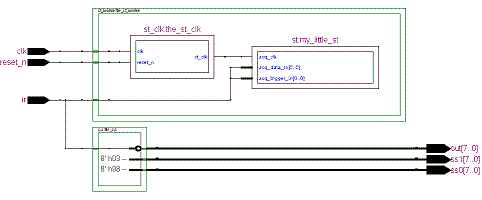
Well, I've changed my testbench design a bit, for testbench 04. I've moved my actual system logic into a module, "sys", and there's a new module, "st_module", for everything related to signaltap. Here's the system top-level, as a block diagram (click for a full-size, more-legible view):

block_diagram_thumb.gif

There's not much to say about module "sys"; it just drives the green LEDs from the IR signal, and puts the testbench ID on the seven-segment display, just like testbench 03 did. But what's going on in module "st_module"? There are two sorts of things:

  1. Some ancillary logic for signaltap. Module "st_clk" creates a low-frequency (390625 Hz) square wave by dividing down the 50 MHz input clock. See "st_clk.v" for the nitty gritty.
  2. An instance of my signaltap probe, "st". The probe has three ports:
    1. .acq_clk (st_clk): this is the signaltap sampling clock.
    2. .acq_data_in (data_in): this is the data signal to sample (driven from the IR receiver's output).
    3. .acq_trigger_in (data_in): oddly, I'm wiring the IR data signal into another port, the trigger input. This will make sense when I describe data acquisition, below.

3. Capture and view trace data:

First, I compile the design and download the sof (using the script "go.sh"). Then, there's just one more thing to do: Quartus' signaltap application requires a file of type "stp". This file stores the trigger configuration, signal aliases and other stuff which doesn't belong in the signaltap probe instance. (Changing the stp file generally won't require a recompile.) In other signaltap flows, creating the stp file is a tortuous and labor-intensive process involving the dreaded Node Finder. With this HDL-centric flow, I create my stp file with a click of the mouse, using menu item:

File/Create|Update/Create SignalTapII File from Instance(s)

I specified file name st.stp (lacking any more creative ideas), and opened it with:

File/Open/st.stp

Then the signaltap GUI connects to the hardware and it's time to configure my trigger, then acquire some data.

The signaltap GUI consists of multiple windows, with many selections disabled (most parameters are only alterable via the Signaltap Megawizard). Somewhere in there, though, there's a window for defining basic trigger levels, like this:

st_trigger_before.GIF

I Right-click on the trigger level for acq_trigger_in[0] and select "Falling Edge":

st_trigger_after.GIF

Now the probe is configured to start capturing data on a falling edge of the IR input signal.

Next, I start pushing the DISPLAY button on the Xbox remote control, to create an interesting data stream, and click the "Run Analysis" button:

run_analysis.GIF

After a few seconds, I get: trace data!

st_trace_display.GIF

It's in an inconvenient graphical form, but data is data. Fortunately, Quartus lets me export the data to various text formats. That'll come later.

Now that I'm looking at and thinking about my data, I can already see that something funny is going on. Even if I don't push any buttons on the Xbox remote control, the signaltap probe is triggering, and I get data like this:

st_trace_noise.GIF

I can also see this on the green LEDs: just sitting on the table, even if I cover the IR receiver, the LEDs are flickering away randomly, pretty much continually. After I push a button on the remote, though, there's up to a second of no flickering - then the flicker is back. Perhaps an AGC artifact?

A dim half-understood fact about high-gain amplifiers and oscillation is surfacing in my memory. I'll think about this problem next - if possible, I want to eliminate this noise from my data stream.

tb_4 files

July 29, 2007

Start Making Sense

By the way - last time I noted a lot of random noise in the IR signal. I decided to build another IR module circuit (IR receiver, resistor, capacitor), this time with the components socketed, so I could more easily debug the problem. Lo and behold, the new circuit has no noise. At some point I'll disassemble the first IR module and swap its parts into the new circuit to see if I can blame the noise on a defective component, but for now, I'd rather do something more fun: decipher the Xbox remote codes.

First off, a fundamental fact about IR communication. The usual milieu for such communication is a noisy environment inhabited by naive yet fault-intolerant users. Transmission is expected to work perfectly, even if the batteries are weak and the user is pointing the remote at the wrong device. The IR receiver compensates for a lot of these problems in its cascade of analog circuits (here), and it performs admirably, but all that circuit can detect is full-on (mark) and full-off (space). So, for any given remote, for each of its buttons, a particular sequence of mark and space durations will be transmitted. The set of possible sequences, and their interpretation into data, is the protocol.

Long ago, before the Internets, I would have had to pore over traces of mark-and-space durations, seeking the elusive pattern of the protocol. Well! That would have been good clean fun. However, on the Internets I see that someone has already done that part. The Xbox remote allegedly conforms to the "RCA protocol". To summarize:

  • 4ms mark, 4ms space begins a transaction.
  • The data is in "pulse distance protocol": each bit consists of a 500μs mark, followed by either 1ms space (logical 0) or 2ms space (logical 1).
  • 24 bits are sent per transmission (4-bit address, 8-bit command, then complement of that same address and command).
  • Address and command are sent MSB-first.
  • Each transmission ends in a final 500μs mark.

I have some experimental data; how well does it match up with that description? Before I answer that question, I'm afraid I'm going to indulge myself in a little rant.

Signaltap's Tragic Flaw

I thought I had a great flow going here. My input was a handful of verilog files and a tcl script for each stage of the flow. I was making good progress (I thought) toward a data collection system which would work like this:

  1. I type "make" (or something)
  2. The fpga configuration file is built, if necessary (if any of its dependencies changed)
  3. The fpga is programmed from its configuration file
  4. I'm prompted, "type the name of a remote control button, then press that button, or <esc> to quit"
  5. I do it, and the signaltap data for that button is captured and logged
  6. After enough data logging, I type <esc> and data for each button is written to a report file.

I can do everything up to step 5), but step 6) appears to be impossible! Why? When, via a tcl script, signaltap is instructed to capture data, the captured data goes into the stp file. (That file looks like some form of XML.) But there are no scripting commands (at least that I could discover) which make stp file data available for further processing. I'm sure I could figure out the format of the XML file and get the data, but that just seems deeply wrong. So sad.

Fallback position: The GUI does provide a way to export signaltap data into various formats. I'll convert my data using the GUI, then work on it in Excel. It'll work, but it will be very time-consuming. Oh, well.

Onward! An example: DISPLAY

Is my Xbox remote really transmitting according to the RCA protocol? I'll have a look at the data that's transmitted when the DISPLAY button is pressed. Here's the sequence of pulse durations that occur, in milliseconds. (I admit to begging the question in the suspicious display format I've chosen.) The first pulse is a "mark" (active transmission, and logic low on the ir signal). Each subsequent number is the duration of a pulse of opposite type to its predecessor.

4,4,
0.5,1,0.5,2,0.5,1,0.5,2,
0.5,1,0.5,1,0.5,2,0.5,1,0.5,2,0.5,1,0.5,2,0.5,1,
0.5,2,0.5,1,0.5,2,0.5,1,
0.5,2,0.5,2,0.5,1,0.5,2,0.5,1,0.5,2,0.5,1,0.5,2,
0.5

Now, if I believe the RCA protocol description, each sequence "0.5,1" is a logical 0, and each "0.5,2" is a logical 1. And I can strip off the 4 ms mark-space at the beginning, and the terminal 0.5ms mark. The result:

0 1 0 1 
0 0 1 0 1 0 1 0 
1 0 1 0 
1 1 0 1 0 1 0 1 

As predicted, I see 12 bits (4 address, 8 command) and then their complements. Here's the beginning of a table:

Button Address (hex) Command (hex)
DISPLAY 5 2A

Next up: I'll fill in the rest of the table. There are 27 buttons on the Xbox remote - this will be tedious.

Postscript: I lied. The mark/space durations above matched the RCA protocol perfectly. But it just isn't true! Unless, that is, I quantize to 1 decimal place, as I did for the data above. If I look at my data with a higher-resolution lens, I see a less tidy picture. This table shows the discrepancies, which are accurate to one signaltap period (5.12μs):

Duration type Protocol prediction My measurement
Initial Mark 4ms 4.0448ms
Initial Space 4ms 3.9782ms
Bit-start Mark 0.5ms 0.5325ms
Logical-0 Space 1ms 0.9677ms
Logical-1 Space 2ms 1.9712ms

Here are some hypotheses which would explain the discrepancies:

  1. The author of the RCA protocol quantized to 1 decimal place.
  2. Xbox remotes are not particularly accurate - mine just happens to be a bit out of whack.
  3. Something in my experimental setup is introducing a systematic error into my measurements - notice that each "mark" value is slightly larger than expected, while each "space" value is slightly smaller.

Mulling over these hypotheses will give me something interesting to do while I go about the rote business of collecting and translating the data for the button-to-code table.

tb_5 files
About July 2007

This page contains all entries posted to Aaron's Sandbox in July 2007. They are listed from oldest to newest.

June 2007 is the previous archive.

August 2007 is the next archive.

Many more can be found on the main index page or by looking through the archives.

Powered by
Movable Type 3.31