So, back to the concept. I'm adding remote on/off capability to my XBox, similar to what's described here. That site informs me that a 56KHz, 3.3V IR Detecting Unit is the one I want, and Sharp's GP1UE267XK looks ok. But, why not just use an IR phototransistor for the task? Here's a hint from the data sheet: the block diagram of the GP1UE267XK looks like this:
There's a lot going on here beyond simple transduction of infrared light into a flow of electrons. The end result of all that circuitry should be better noise resistance (fewer false triggers) and better detection of weak signals. Digikey sells the device for $1.08, and that seems like a pretty good deal to me.
Here's a good discussion of how IR remote controls work.
It's worth noting here that in choosing the GP1UE267XK, I'm already moving away from a general-purpose IR receiver design, because of the device's 56.8kHz center frequency. To get back to generality, I'd have to consider using pluggable IR receiver modules, specific to each application frequency, or the use of a more general-purpose receiver circuit.
Here's how the data sheet suggests hooking up the GP1UE267XK:
The data sheet also has this advice, which I will surely follow to the letter:
![]()
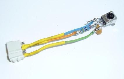
Now. The GP1UE267XK and its associated resistor and capacitor form a 3-pin module, which I've soldered to a connector:
The IR module will plug into the santa cruz connector board, but where?
- pin 3, GND (green wire): Easy, connect this to any handy ground point on the santa cruz board.
- pin 2, Ve (orange wire): Also easy, connect to any +3.3V point on the santa cruz board.
- pin 1, Vo (blue wire): Hm. This requires some thought. Connect it to one of the pins on the header that the f2013 plugs into?
I've decided. Vo will connect to a currently-unused santa cruz connector signal which drives the 1c20. Then I can route Vo through the 1c20 to any f2013 microcontroller pin. I can also use the 1c20 testbench circuitry to analyze the IR signal, or even create 1c20 testbench circuits to simulate known IR signals, for regression testing.
Here's the IR module, plugged into the santa cruz connector board:
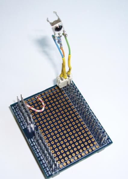
Vo (blue wire) connects to the signal labeled "P0" on the santa cruz connector board silkscreen, which in turn connects to 1c20 pin T15.
New testbench time! This one will be revision "03", and it'll simply connect the signal from the IR module, through the 1c20, to the 8 LEDs. The goal here is just to demonstrate that the IR module is alive and can receive a signal from the remote. Here's the system in action:
Success! The LEDs blink in response to a signal from the remote. But what's the encoding protocol? What codes are sent for each key? Is there parity or some other error detection scheme embedded in the data? To find out all this and more, I'll need the assistance of a mighty tool, SignalTapII(tm). Next time!