So, I've replaced a simple, cheap breadboard containing a few wires and an LED with an expensive, very complex circuit board containing, among other things, an FPGA which is much more sophisticated than the microcontroller I want to use. I'm depressed. What was the point, again?
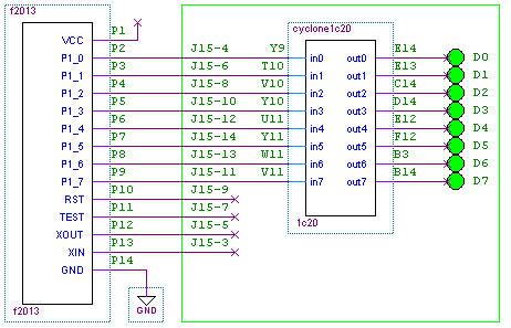
To restore my optimism, I need to see some tangible results. I'll start with a nice simple application. The first testbench configuration for the FPGA will consist only of pins and wires; everything else in the FPGA will be left idle. Here's a block diagram of the system:

All of the microcontroller's pins (except VCC and GND) connect to the 1c20 board through J15, but in this design I'll only use 8 pins: P1.0 - P1.7. The FPGA will just be wires - it'll connect in0 to out0, in1 to out1, et al. The 8 outputs, out0 - out7, will drive the 8 individual LEDs on the 1c20 board. Then I'll write some code for the f2013 which will drive a recognizable pattern onto P1.0 - P1.7, which will make the 8 LEDs blink. Sounds easy! But... how do I configure the FPGA?
Install the Altera design software (Quartus)
A free version of Altera's main design tool, Quartus, is available. Go to http://www.altera.com and look for the "Quartus Web Edition Software". I hope the installation procedure is self-explanatory. If you run into trouble, let me know.
Create and configure a quartus project
This can be done via the GUI, but I think I'll play with the scripting flow. This is based on tcl, which seems to be the lingua franca of the EDA world. Altera provides a command-line tool which executes tcl files, and a set of commands which manage projects, set design properties, etc. I'll only scratch the surface here. Let's get started! I created a tcl script, call it tb_1.tcl:
#  Step 1: Create a new project called tb_1

project_new tb_1

project_open tb_1
# Step 2: Project settings:
# a. Choose the type of FPGA
set_global_assignment -name FAMILY Cyclone
set_global_assignment -name DEVICE EP1C20F400C7
# b. Any pins which aren't otherwise defined should be inputs.
set_global_assignment -name RESERVE_ALL_UNUSED_PINS "AS INPUT TRI-STATED"
# c. Declare the top-level file (well, the only file):
set_global_assignment -name VERILOG_FILE top.v
set_global_assignment -name TOP_LEVEL_ENTITY top
# Step 3: Set pin assignments. This is where the top-level ports of the testbench
# design are mapped to actual physical FPGA pins.
set_location_assignment PIN_Y9 -to in[0]
set_location_assignment PIN_T10 -to in[1]
set_location_assignment PIN_V10 -to in[2]
set_location_assignment PIN_Y10 -to in[3]
set_location_assignment PIN_U11 -to in[4]
set_location_assignment PIN_Y11 -to in[5]
set_location_assignment PIN_W11 -to in[6]
set_location_assignment PIN_V11 -to in[7]
set_location_assignment PIN_E14 -to out[0]
set_location_assignment PIN_E13 -to out[1]
set_location_assignment PIN_C14 -to out[2]
set_location_assignment PIN_D14 -to out[3]
set_location_assignment PIN_E12 -to out[4]
set_location_assignment PIN_F12 -to out[5]
set_location_assignment PIN_B3 -to out[6]
set_location_assignment PIN_B14 -to out[7]
# Step 4. That's all!
project_close
To execute this tcl script, I go to an empty directory, open a bash shell (use Quartus' version, in <quartus>/bin/cygwin/bin/, if you don't already have one handy), and run
quartus_sh -t tb_1.tcl
Now the directory contains a few new things: files tb_1.qsf and tb_1.qpf, and a db directory. The qsf file seems to be nearly a copy of tb_1.tcl, with some extra stuff added. Comments in the qsf file advise me not to modify the file. Well, ok.
Specify the design's logic
In tb_1.tcl, I declared that the project's top-level entity would be "top", and that there would be a verilog file called "top.v". To deliver on my promise, I must create a verilog file called "top.v" which defines a module "top" containing all the ports that I made pin assignments for. Here's that verilog file:
module top(

  in,

  out

);
input [7:0] in;
output [7:0] out;
assign out = in;
endmodule
Compile the design
Another tcl script, tb_1_compile.tcl:
# Compile the project:

# quartus_sh -t tb_1_compile.tcl

load_package flow

project_open tb_1

execute_flow -compile

project_close
Executing this tcl script takes 1 minute 22 seconds on my ancient laptop. The result is the FPGA configuration file, tb_1.sof.
Configure the FPGA
I've got a USB-Blaster for configuring my board. Here's the gratuitously-obscure command to configure the FPGA:
quartus_pgm --mode=jtag --cable=USB-Blaster --operation=p\;tb_1.sof
Results and wrapup
With the f2013 plugged into the santa cruz connector board plugged into the 1c20 board, a USB cable plugged into the f2013 (for power) and tb_1.sof downloaded into the FPGA, I actually do see blinking lights on the 8 LEDs! This is the result of whatever simple program I last programmed into the f2013. Next time I'll start fresh with a new f2013 software project, and blink some LEDs intentionally.
Comments (1)
I ended up in this page while looking for USB-JTAG Cables, isn't that funny?
Posted by silvio | August 28, 2007 11:01 PM
Posted on August 28, 2007 23:01