An unexpected puzzle came up - a component which seems simple, but turns out to be rather annoying to implement. A good test case, I say. I'll make this quick and brief - the new component files are attached below if you want to dig deeper.
The component's Family/Genus/Species is Adapter/Avalon-ST adapter/Avalon-ST Error Adapter.
Adapter
An adapter, generally speaking, is a simple component which is inserted in between a pair of components of a particular type, to accomplish some sort of conversion. A typical example is the data-width adapter (to allow connection of, say, an Avalon-MM master and slave, or an Avalon-ST source and sink, which happen to have different data widths). A good adapter is fairly simple, does only one thing, and is completely parameterized according to information from the interfaces it connects to.
Avalon-ST Adapter
Adapters of this description are tailored to the particular set of signals supported by Avalon-ST. These adapters understand the specific direction of Avalon-ST signals (e.g. the "data" signal is an output from a source, and an input to a sink; the "ready" signal is an input to a source, and an output from a sink).
Avalon-ST Error Adapter
This adapter does straight-through wiring on all Avalon-ST signals except for one, the "error" signal. All signals other than "error" are required to have the same bit width on both the source and sink which the adapter is connects to. And that's where the regularity ends: the "error" signal is wonderfully free to vary. The source may have no error signal, or a multiple-bit one; likewise on the sink. With mismatched widths, how can the adapter do its job? Well, one more thing about the error signal: each individual bit of the error signal has a "type", which is an arbitrary string, or the special string "other". Given a "type map" for all the source and sink error bits, there are some simple rules for error signal adaptation:
- Like-type error bits are directly connected
- If the sink has an error bit of type "other", it's driven by the logical OR of any as-yet unconnected source error bits (type "other" or otherwise).
- If any undriven sink error bits remain, they are driven with 0.
- Any remaining unconnected source error bits are ignored.
Huzzah, a new base class
Since any Avalon-ST adapter will have a mess of same-width signals which wire straight through, and then maybe one signal which needs some special treatment, it makes sense to derive a base class (avalon_st_adapter) from europa_module_factory, from which all Avalon-ST adapters will further derive. This base class calls into a derived class method for doing any special signal handling, then does straight-through wiring on any remaining (non-special) signals. The derived class is concerned only with doing its special job on its special signal(s), and managing any options relevant to the special signal(s).
Command-line args - limited to simple numerals and strings thus far
But that's far too limiting. Here's why: avalon_st_adapter is a component in its own right, though really a silly one. Its generation parameters are a set of signal descriptions (name, width and type) on its "in" (driven by the source) and "out" (driving the sink) interfaces. It's natural to think of these input parameters as a simple pair of hashes, keyed on signal type. But I want to retain the guideline of pure command-line specification of parameters. I could encode those hashes as comma-separated lists of things, to be massaged and processed by a script into proper perl data structures, but that seems like a lot of work. What to do? No problem, I simply pass my hashes in perl syntax on the command line, appropriately escaped, and "eval" does the parsing for me. Validation of these non-scalar fields presents a bit of a nuisance, but nothing that can't be dealt with. For now, I simply validate against the field "type" (HASH, ARRAY, CODE, undef-for-scalar), but nothing stops me from (in the future) defining nested parameter data structures which encode the same sorts of value sets and ranges that I already use for scalar parameters.
To the basic set of port declarations which form avalon_st_adapter's generation parameters, avalon_st_error_adapter adds two more hashes, in which the "in" and "out" interface error bit types are described.
Testing, testing...
Once I had the basic avalon_st_adapter class working, and a skeleton implementation of avalon_st_error_adapter, I found myself doing lots of exploratory refactoring. I worried that I'd break the functionality, which I was happy with. Solution: unit tests. In my case, this means, for each component, a handful of test-case scripts, each of which produces an HDL module, and a top-level test script, "test.sh". After making a change, I run ". test.sh", which runs all the test cases and diffs the output HDL against a set of "known-good" files in a subdirectory. Occasionally, a change is made which does change the output HDL, and for those cases, I carefully examine the new and old files to convince myself that the new HDL file can replace the old known-good one (or note that I've created a new bug, and fix it).
Avalon-ST signal type "error": wonderfully free form
Actually, this is rather an annoying adapter, due to the unconstrained nature of the "error" signal. You'll note that all of the nuisance is concentrated in avalon_st_error_adapter::make_special_assignments().
HDL comments
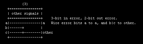
I went a bit out of my way to produce comments on the adapter assignments, to label the signals and error bit types. Here's a nice ascii block diagram of error adapter test case "3":
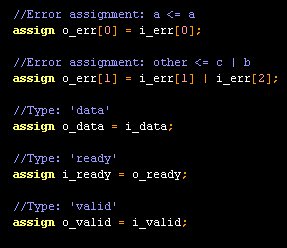
... and here's a snippet of of test case 3's HDL implementation, showing handy assignment comments:
That's it for now. For all my most ardent fans, I'm attaching the new avalon_st_adapter and avalon_st_error_adapter components, along with their test scripts and known-good HDL files. I'm also including the latest version of europa_module_factory, which changed slightly to support the new command-line processing.
Comments (5)
Aaron,
I'll comment on one of my favorite things ever: Schematics! Your ASCII block in this post as well as a small ASCII block diagram several posts back I found very useful.
Indeed, in the product we are affiliated with in our day-jobs we used to (and I advocated) shipping our examples with a top-level schematic. Adding or removing ports was a breeze, as was quickly grokking the big-picture of the top-level of a design that has several interfaces. Someone decided it was too much trouble to maintain these (by hand). The result (for me, when playing customer and modifying a design) is the tedium of several minutes of text editing in what used to be a few mouse clicks, and then highlighting/cutting/pasting a group of pins in a schematic editor to shuffle them around when making way for a new top-level signal.
I'm not necessarily advocating schematic-based design top-to-bottom, no -- generating RTL and wiring it together is fine by me, but my human mind is so much more efficient at looking at a picture versus scanning a port-list, and then later in the RTL whether each port is an in/out/bidir.
So, I thank you for your ASCII art and I say keep it up!
Posted by Jesse | November 21, 2007 12:14 PM
Posted on November 21, 2007 12:14
Jesse,
I also lamented the end of the example design top-level bdf, though I understand that maintaining them was a major headache. Whenever I receive a customer design in a bug report, I'm much happier to see a top-level bdf than top-level HDL, because (as you say) it's easier to get the big picture from, well, a picture.
The root of the problem with bdf is the bdf semantics, which consists of descriptions of rectangles and other basic objects, with size and position values. Connections (say between a symbol port and a wire) are made whenever the objects are at the same location. Thus when a symbol changes its size or port ordering, disconnection is likely. A better semantic would leave object position unassigned ("auto" assignment) and provide a way to express explicit connection. It would be up to the bdf viewer tool to try to place objects in an orderly fashion; in the worst case the picture might be a bit unclear, but connections would be maintained.
Thanks for your timely comment about ascii art - timely because I'm right now struggling with some more ascii block diagrams, so it's good to know someone's actually looking at them!
Posted by Aaron | November 22, 2007 9:57 AM
Posted on November 22, 2007 09:57
Aaron,
Thanks to your blog, I looked into Europa also a bit, and I came across some other verilog generating systam called 'MyHDL'. It's not Perl, its Python. It has the nice feature that you can simulate your design with Python, writing unit tests if you want to, and generate verilog code from it.
http://myhdl.jandecaluwe.com
Posted by Stefaan | December 30, 2007 2:28 PM
Posted on December 30, 2007 14:28
Stefaan, thanks for your comment! I had heard of myhdl long ago, but haven't looked at it recently - in light of my current projects, it's looking very interesting. I'm going to learn enough about it to create a simple component using it, and post about the experience here.
Posted by Aaron | January 2, 2008 8:37 AM
Posted on January 2, 2008 08:37
If you have some questions, give me a sign.
Posted by stefaan | January 4, 2008 1:44 PM
Posted on January 4, 2008 13:44